Verilog for design and verification is a 10-week course focused on Verilog for complex design implementation and verification with daily hands-on labs.
Next Batch
1-1 Dedicated Mentor Support
24/7 Tool Access
Multiple Mock Interviews
Industry Standard Projects
Support with Resume Update
Verilog Course Overview
Course Overview
Verilog for Design & Verification is a 10 weeks course with detailed emphasis on Verilog for complex design implementation and verification. Verilog course helps both design and verification engineers to gain expertise in Verilog for RTL coding and test bench development.
Every aspect of Verilog course is supported with multiple examples to make the learning easier. Course also covers multiple design implementation examples and test bench setup for the same, and all these done from scratch.
Lab sessions are planned everyday to enable student work on these projects from scratch with trainer guidance.
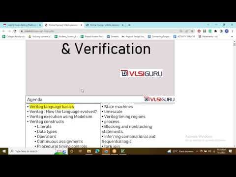
- Verilog language basics
- Verilog: How the language evolved?
- Verilog execution using Modelsim
- Verilog constructs
- Literals
- Data types
- registers, nets
- Vectors, Array
- Operators
- Various styles of Modeling: Data Flow, Behavioral, Gate level, Switch level
- Continuous assignments
- Combinational logic coding : Half adder, full adder, multiplexer, comparator, encoder, decoder, priority encoder
- Generate
- Procedural timing controls
- task and functions
- system task and function
- modeling memories and FSM
- Parameters
- Port connections
- Procedural blocks
- Sensitivity list
- State machines
- timescale
- Verilog timing regions
- process
- Blocking and nonblocking statements
- Inferring combinational and Sequential logic
- Clock generation with Duty cycle & Jitter
- Shift register implementation
- Procedural Blocks
- fork join
- Race conditions
- Synthesis examples
- Inter and Intra delay statements
- example to showcase race condition using blocking assignments
- Pipelining
- Memories
- Structural modeling
- Verilog Programming Interface(& PLI)
- PLI
- compiler directives
- system task usage: $display, $monitor, $strobe
- PLI, VPI implementation
- Primitive implementation using table, endtable

Key Features
Who All Can Attend This Verilog Course?
This Verilog course welcomes engineering graduates and diploma holders from ECE, EEE, CSE and IT backgrounds, as well as job seekers, career changers and anyone keen to learn VLSI design and verification using Verilog.Pre-requisites To Take Verilog Course
To make the most of this Verilog course, learners are expected to have:
- A basic understanding of digital electronics and logic design
- Familiarity with Boolean algebra and binary number systems
- Fundamental knowledge of programming concepts (any language)
- An interest in hardware design, VLSI or FPGA development
Prior experience with HDL (Hardware Description Languages) is not mandatory, as the course starts with Verilog fundamentals.

High Demand for Verilog Course
Know about the Growing VLSI industry
Responsible for designing and coding RTL modules in Verilog, writing synthesizable digital designs, and simulating functionality for complex semiconductor chips.
Over 80% of VLSI design companies require Verilog skills for front-end design and verification roles.
Verilog proficiency increases employability by 50% and is essential for roles in ASIC, FPGA, and SoC development.
Verilog-trained engineers are highly sought after in India’s growing semiconductor sector, which is expected to reach $105 billion by 2030 with robust government and industry support.
₹8 LPA


Explore a wide range of VLSI and Embedded Systems courses to get industry-ready.
50+ industry oriented courses offered.

Explore a wide range of VLSI and Embedded Systems courses to get industry-ready.
50+ industry oriented courses offered.